Wiring Diagram For Ge Rr9
Switch voltage low ge relay relays kyle plates replaced determine needs guide which use part first Switch low voltage ge system wiring diagram rr7 relay lighting kyle plates P&s sierra low voltage switch & relay wiring guide
GE Lighting Control System with 6 RR9P Relays and an 8-Group Input
Ge rr9 wiring diagram Ge rr8 relay wiring diagram collection Ge voltage low relay switch diagram wires kyle plates coming where these
Ge rr7 wiring diagram awesome
Ge rr9 relay wiring diagramRr9 wiring ge diagram Rr9pbpWiring ge relay voltage.
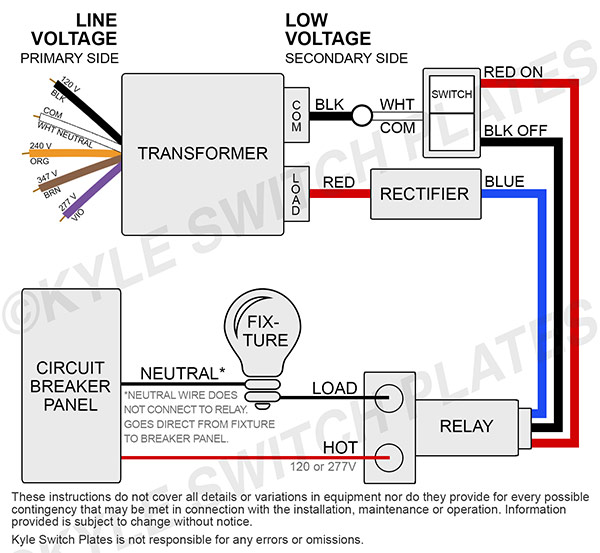
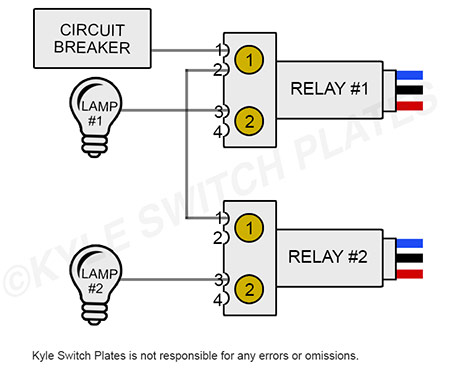
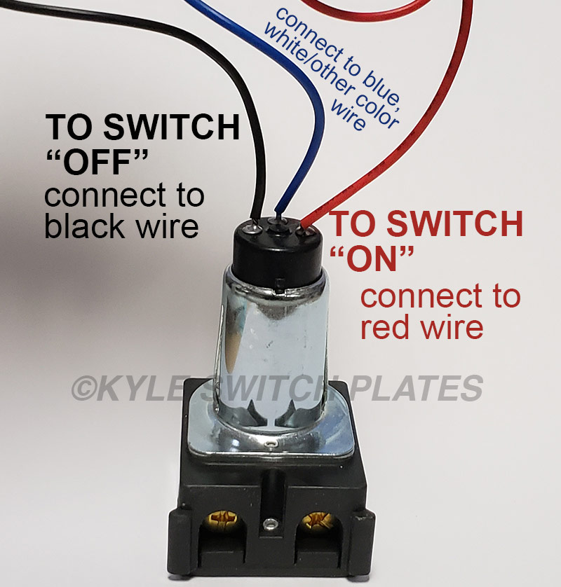
Ge voltage low relay wiring lighting relays switch wire diagram circuit guides faq help breaker kyle plates multiple setup shownGe low voltage switch & relay wiring instruction guide Relay voltage low ge switch rr3 wires kyle rr7 replace plates rr2 rr5 labeled if old hasRelay ge wiring rr9 rr4 voltage rr7 switches relays applicable conform schematron.
![Ge Rr9 Relay Wiring Diagram - Wiring Diagram Pictures](https://i2.wp.com/schematron.org/image/ge-rr9-relay-wiring-diagram-8.jpg)
Wiring diagram ge rr7 rr4 awesome source
Ge rr7 wiring diagram awesomeGe low voltage lighting system help guides, wiring diagrams, lo vo faq Switch instruction relays sierra transformers switchesKyle switch plates: how to replace a low voltage ge switch & relay.
Ge rr9 wiring diagramGe rr9 relay wiring voltage switches rr Relay ge voltage low wiring lighting switch diagram guides faq help locate two screws multiple brass base four then sideGe lighting control system with 6 rr9p relays and an 8-group input.
![RR9PBP - Latching Relay With 5-Pin Connector](https://i2.wp.com/cdn.chipkin.com/assets/uploads/2019/Aug/RR9P Drawing_29-12-28-34.png)
Ge rr9 relay wiring diagram
Diagram wiring ge rr7 relay rr8 awesome nl sourceRelay connector latching Kyle switch plates: august 2018Wiring diagram ge rr8 relay collection victron inverter read.
Relay input relaysGe lighting control system with 24 rr9p relays, and an 8-group input Kyle switch plates: how to replace a low voltage ge switch & relayKyle switch plates: august 2018.
![Ge Rr7 Wiring Diagram Awesome | Wiring Diagram Image](https://i2.wp.com/mainetreasurechest.com/wp-content/uploads/2019/07/ge-rr7-wiring-diagram-elegant-ge-rr4-wiring-diagram-of-ge-rr7-wiring-diagram.jpg)
Ge rr9 relay wiring diagram
Kyle switch plates: how to replace a low voltage ge switch & relayRelay wiring rr9 ge diagram pilot stripped leads isolated wire contact Relay wiring ge diagram rr9 addressable modules lighting.
.
![Kyle Switch Plates: August 2018](https://1.bp.blogspot.com/-AtnLBfagpmw/W370k8Dtd-I/AAAAAAAABxU/TmyksvQkDXIdYZa4Jk1Q9yKrf7FZkkZcgCLcBGAs/s640/blog-ge-low-voltage-system-wires-parts-diagram-larger.jpg)
![Ge Rr9 Relay Wiring Diagram](https://i2.wp.com/schematron.org/image/ge-rr9-relay-wiring-diagram-5.png)
![GE Lighting Control System with 6 RR9P Relays and an 8-Group Input](https://i2.wp.com/cdn.chipkin.com/assets/uploads/2018/Aug/RR7P Relay Operation_21-14-25-46.png)
![GE Low Voltage Lighting System Help Guides, Wiring Diagrams, Lo Vo FAQ](https://i2.wp.com/cdn1.bigcommerce.com/server3900/wlejmk/product_images/uploaded_images/info-wiring-1-ge-relay-diagram-of-parts.jpg)
![Kyle Switch Plates: How to Replace a Low Voltage GE Switch & Relay](https://4.bp.blogspot.com/-IarvS5LhmNI/W3yGfUccvLI/AAAAAAAABsc/U-E-IncwmSQKoiuG7cJx-570BiLHA5vYQCLcBGAs/s1600/info-wiring-2-ge-relays-diagram-of-parts.jpg)
![Ge Rr9 Relay Wiring Diagram](https://i2.wp.com/schematron.org/image/ge-rr9-relay-wiring-diagram-2.jpg)
![Kyle Switch Plates: How to Replace a Low Voltage GE Switch & Relay](https://3.bp.blogspot.com/-kDPi0x32iEU/W4gifWmsgAI/AAAAAAAABzM/l3PloC0cjv0CP2Mo-Bz9006PsRlxwiyIgCLcBGAs/s1600/blog-ge-low-voltage-relay-wires-explained-red-black-blue.jpg)
![GE Low Voltage Switch & Relay Wiring Instruction Guide](https://i2.wp.com/cdn11.bigcommerce.com/s-wlejmk/images/stencil/320w/products/4455/23122/GE-WIRING-KSP-THUMBNAIL__03539.1530129527.jpg?c=2)
![GE Lighting Control System with 24 RR9P Relays, and an 8-Group Input](https://i2.wp.com/cdn.chipkin.com/assets/uploads/2018/Aug/Typical Electronic Driver Circuit ULN-2003A_21-14-25-41.png)